


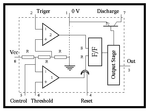
Figure: The 555 internal circuit
The 555 circuit is consisted by two comparators, one ohmic ladder one flip-flop and a discharging transistor, as it is shown in figure
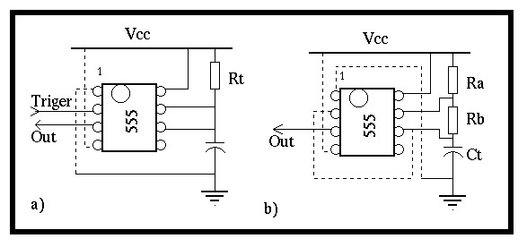
Figure: The 555 modes of operation a) monostable b) astable (multivibrator).
This circuit can be connected as a monostable multivibrator or an astable multivibrator.
The 555, connected as a monostable is shown in figure 1.1
equation: T=1.1 Rt*Ct
Were T is the output pulse high period, Ct the charging
capacitance measured in Farads and Rt the charging resistor in Ohms. If the
circuit is connected as an astable multivibrator (figure 1.1
equation: Th=0.7(Ra+Rb)Ct
While the time for the low period is given by the
equation: Tl=0.7 Rb*Ct
The obvious observation from the above equations is that the duty cycle of the oscillator is always bigger than 50%. Or in other words the charging time is always bigger that the discharging period, since Ra+Rb>Rb taken in account that Ra>0. Yet if Ra>>Rb then a 50% duty cycle can be approximated.