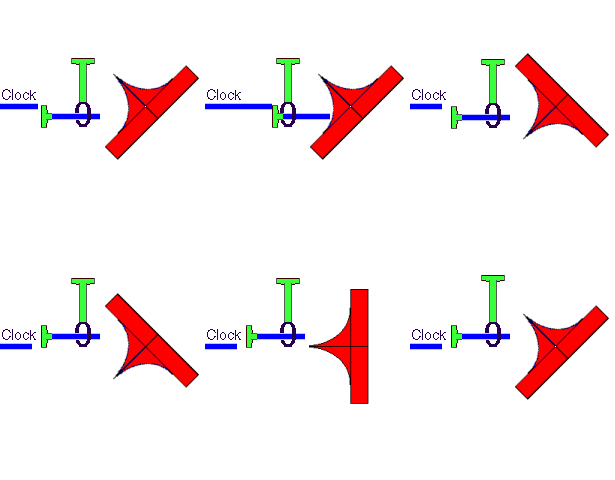
"Real
World" DOs
& DON'Ts
What
should I do with the UNUSED INPUTS?
TTL devices normally default to a logic ONE if the input is allowed to FLOAT.
However, depending on many factors, these inputs can act as an antenna,
and pick up NOISE which can cause mischief to the circuit. The worst case
is, the device will act as an uncontrolled intermittent OSCILLATOR.
--This is BAD!
Therefore:
ALL unused inputs of TTL logic devices IDEALLY should be returned to either
a logic ONE or logic ZERO. Certain devices--74XX and earlier 74LS--the logic
ONE (Vcc) should be a ~ 1k resistor to Vcc; or alternatively, connected directly
to ground (ZERO). Most/All other logic devices, the resistor is UNNECESSARY.
In the case of CMOS devices, there is NO input DEFAULT; CMOS input impedance
is on the order of thousands of MEGOHMS and will cause EXTREME FAILURES if
allowed to FLOAT.
To make this point: if you put your finger or a scope probe on or NEAR
an un-terminated CMOS input, it can cause a logic CHANGE!! If allowed
to float, some CMOS devices can oscillate so fast, that it exceeds the device
power rating and will literally destroy itself.
Unused Outputs--tri state, open collector, etc., DO NOT require any attention.
NOTE: In the case of the tristate control pin, it should be treated as an
INPUT.
NEVER EVER USE the original generic 7400 DEVICE.
INSTEAD: Use anything else, e.g., 74LS, 74ALS, etc.
The older devices require five to ten times the drive power and force very LARGE
amounts of NOISE on to the Vcc
rail! --This is NOT GOOD!
Remember, the newer the technology the happier the circuit will be--well
almost!
TRUE
= 1 = YES = POSITIVE = MARK
FALSE = 0 = NO = NEGATIVE
= SPACE
NOT
= INVERSION
That is: if a FALSE is Inverted (NOT), it becomes a TRUE
Likewise: if a TRUE is Inverted (NOT), it becomes a FALSE.
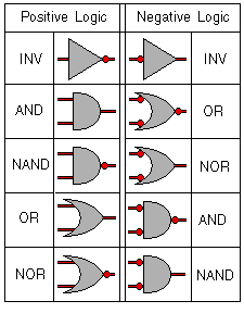
A NOT or Inversion is usually indicated by a Bubble, on either the input
or the output of a logic gate symbol.
The convention (which is not always adhered to) is that a POSITIVE Gate
Inversion is indicated by a bubble on the output, and with Negative logic
the bubble is at the input.
See
Symbol Examples
Binary
Codes
Number
Decimal
fraction
Two's
complement
One's
complement
Sign
+
magnitude
Offset
binary
+7
+6
+5
+4
+3
+2
+1
+7/8
+6/8
+5/8
+4/8
+3/8
+2/8
+1/8
0111
0110
0101
0100
0011
0010
0001
0111
0110
0101
0100
0011
0010
0001
0111
0110
0101
0100
0011
0010
0001
1111
1110
1101
1100
1011
1010
1001
0
0
0+
0-
0000
0000)
0000
1111
0000
1000
1000
1000)
-1
-2
-3
-4
-5
-6
-7
-8
-1/8
-2/8
-3/8
-4/8
-5/8
-6/8
-7/8
-8/8
1111
1110
1101
1100
1011
1010
1001
1000)
1110
1101
1100
1011
1010
1001
1000
1001
1010
1011
1100
1101
1110
1111
0111
0110
0101
0100
0011
0010
0001
0000)
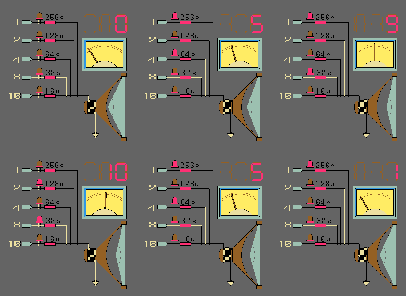
Binary-Decimal-Real
Values
Flip-Flop in--
Flip-Flop in--
Flip-Flop in--
Set Reset Mode
Toggle Mode
Data
Mode
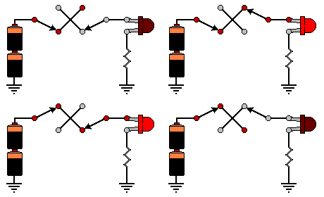
Exclusive OR (XOR)
Using the Same Function --It is also correct to say: In order for the Output
to be FALSE: input (1) & input (2) must both be Identical--11, 00. This is Negative Logic.
Truth
Table->A &
B are the Input switches
C is the Output LED
In
order for the Output of an XOR Logical Function to be TRUE: input (1) &
input (2) must both Different--01, 10. This is Positive Logic.
Positive Logic, Negative Logic Explained using Doors & Switches
In
this animated AND Logic example of Doors Opening and Closing,
you can see that in order for the "Light" to get through the house, the front
door AND the back door must be Open.
Same example: if either the front door OR the back door is Closed
the light does NOT get through.
In
this animated OR Logic example, you can see that in order
to get light through the house: the left-front door OR the right-front
door (or both) must be Open.
Same example: in order to block the light through the house: the left-front
door AND the right-front door must be Closed.
Using the Same Function --It is also correct to say: If either input (1)
OR input (2) (or both) is NOT TRUE the Output Will be FALSE. This
is Negative Logic.
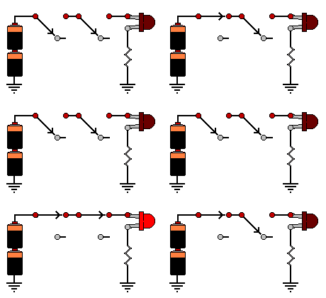
A &
B are the Input switches C is the Output LED
In
order for the Output of an AND Logical Function to be TRUE: input (1) AND
input (2) must both be TRUE. This is Positive Logic. Hint: TRUE
is when the switch is closed, applying power to the LED. FALSE is
when the switch is open, NOT applying power to the LED)
Using the Same Function --It is also correct to say: In order for the Output
to be FALSE: input (1) AND input (2) must both be FALSE. This is Negative Logic.
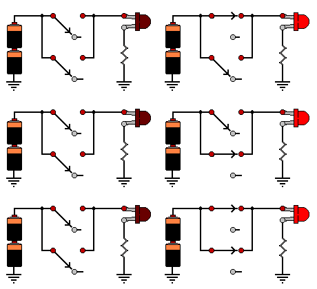
A & B are the Input switches
C is the Output LED
In
order for the Output of an OR Logical Function to be TRUE: either
input (1) OR input (2) (or both) must be TRUE. This
is Positive Logic.
Remember:
1) A Positive AND gate is a Negative OR gate
2) A Positive OR gate is a Negative AND gate
AND Logic Function
using Doors
OR Logic Function
AND Logic Function
using Switches
OR Logic Function
